
Data Center Cooling Systems: CRAC, Liquid Cooling, Containment & PUE Optimization
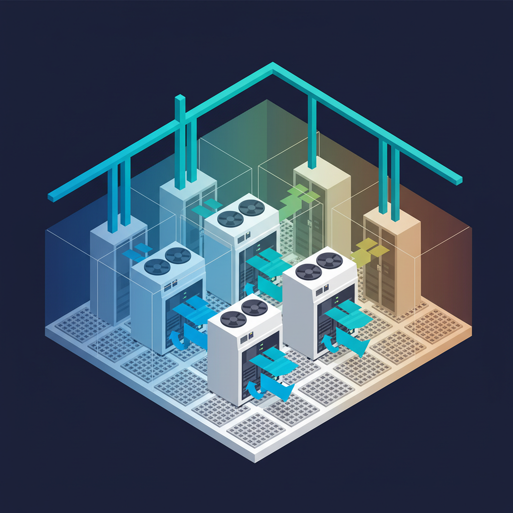
Thermal Management Is the Constraint on AI Density
As GPU rack densities exceed 30 kW, conventional air cooling reaches its limits. DCS Global designs cooling architectures: air, liquid, and hybrid: that support your current density and scale with your AI roadmap.
Cooling Decisions That Protect Your Infrastructure Investment
Precision Air Cooling
Computer Room Air Conditioning (CRAC) and Computer Room Air Handler (CRAH) systems sized and positioned for precise temperature and humidity control, ith hot/cold aisle containment to eliminate bypass airflow and improve cooling efficiency.
Chilled Water Systems
Chilled water plant design and installation including air-cooled and water-cooled chillers, cooling towers, pumping systems, and piping distribution, roviding scalable, energy-efficient cooling for large data centers.
Direct Liquid Cooling
Direct liquid cooling (DLC) for high-density AI and HPC racks exceeding 30 kW, ncluding rear-door heat exchangers, cold plate systems, and full immersion cooling for GPU clusters and liquid-cooled servers.
In-Row Cooling
In-row cooling units deployed between server racks for targeted, high-density cooling, liminating long air paths, reducing fan energy, and enabling higher rack densities than traditional perimeter cooling.
Aisle Containment
Hot aisle and cold aisle containment systems, ncluding hard containment with doors and blanking panels, chimney cabinet containment, and overhead containment: to eliminate hot/cold air mixing and improve CRAC/CRAH efficiency.
Cooling Controls & BMS
Cooling system controls integration with BMS and DCIM, nabling automated setpoint adjustment based on IT load, predictive cooling response, and real-time PUE monitoring and optimization.
Technology Selection
Cooling Technology Comparison
Air-Side Economization
Free cooling using outside air when ambient conditions permit: dramatically reducing mechanical cooling hours and achieving industry-leading PUE in suitable climates.
Rack Density
Up to 10 kW/rack
PUE Range
1.1 – 1.3
Precision Air Cooling
CRAC/CRAH with hot/cold aisle containment: the standard for enterprise data centers with mixed workloads and moderate rack densities.
Rack Density
Up to 20 kW/rack
PUE Range
1.3 – 1.5
In-Row + Chilled Water
Most CommonIn-row cooling units fed by chilled water plant, roviding high-density cooling with excellent energy efficiency and scalability for growing deployments.
Rack Density
Up to 30 kW/rack
PUE Range
1.2 – 1.4
Direct Liquid Cooling
Cold plate or immersion cooling for AI/HPC racks: the only viable solution for GPU clusters and liquid-cooled servers at extreme rack densities.
Rack Density
30 – 130+ kW/rack
PUE Range
1.1 – 1.2
Delivery Process
Cooling System Phases
Thermal Assessment
IT load analysis, rack density mapping, airflow modeling, hot spot identification, and cooling capacity gap analysis against current and projected loads.
Cooling System Design
Cooling architecture selection, equipment sizing, containment design, chilled water plant design, and energy efficiency modeling with PUE projections.
Infrastructure Installation
Mechanical and piping installation, CRAC/CRAH placement, chilled water distribution, containment installation, and electrical connections.
Controls & BMS Integration
Cooling controls programming, BMS integration, DCIM sensor integration, and automated setpoint configuration for load-following operation.
Commissioning
Functional testing, airflow measurement, thermal performance validation, redundancy testing, and PUE baseline measurement.
Optimization
Post-commissioning thermal optimization, containment gap remediation, setpoint tuning, and quarterly performance reviews.
Technical Specifications
Frequently Asked Questions
What cooling system is right for AI and GPU workloads?
AI and GPU workloads typically require rack densities of 30-130+ kW, which exceeds the capacity of traditional air cooling. Direct liquid cooling (DLC) using cold plates or rear-door heat exchangers is the standard approach for GPU clusters. Full immersion cooling is used for the highest densities. We design hybrid cooling systems that support both air-cooled standard servers and liquid-cooled GPU nodes in the same data hall.
What is hot aisle/cold aisle containment and why does it matter?
Hot aisle/cold aisle containment separates the cold supply air from the hot exhaust air in a data center. Without containment, cold and hot air mix, forcing CRAC/CRAH units to work harder to maintain setpoints. Containment typically improves CRAC/CRAH efficiency by 20-40% and can eliminate hot spots that cause thermal throttling. It is one of the highest-ROI improvements for existing data centers.
What is PUE and what can we realistically achieve?
Power Usage Effectiveness (PUE) is total facility power divided by IT equipment power. A PUE of 1.0 is perfect. The industry average is approximately 1.58. A well-designed enterprise data center with containment and chilled water cooling should achieve 1.3-1.4. Facilities with economization can achieve 1.1-1.2. We model PUE during design and measure it after commissioning to validate performance.
How do you size cooling for future growth?
We design cooling systems with capacity headroom and modular expansion paths. For chilled water plants, we size the primary distribution for the ultimate load but install chillers in phases. For CRAC/CRAH systems, we design the raised floor or overhead distribution for full capacity but deploy units as load grows. We also model the cooling impact of planned IT deployments so you can plan infrastructure investments in advance.
What is the difference between CRAC and CRAH units?
A CRAC (Computer Room Air Conditioning) unit has a self-contained refrigeration circuit: t cools air directly using a compressor, condenser, and expansion valve. A CRAH (Computer Room Air Handler) uses chilled water from a central plant to cool air: it has no refrigeration circuit of its own. CRAHs are more energy-efficient at scale because the central chilled water plant can use economization and variable-speed pumping, but they require a chilled water infrastructure investment.
What is water usage effectiveness (WUE) and why does it matter?
Water Usage Effectiveness (WUE) measures how much water a data center uses for cooling per unit of IT energy consumed (liters/kWh). Facilities using cooling towers or evaporative cooling consume significant water: 10MW data center with a WUE of 1.5 uses approximately 131 million liters of water per year. Air-cooled and liquid-cooled facilities with dry coolers have near-zero WUE. WUE is increasingly important for sustainability reporting and in water-stressed regions.
How do you handle cooling for mixed air-cooled and liquid-cooled racks?
Hybrid cooling designs support both air-cooled standard servers and liquid-cooled GPU/HPC nodes in the same data hall. We zone the data hall: liquid-cooled zones have CDUs (Coolant Distribution Units) providing chilled water or facility water to rack manifolds, while air-cooled zones use standard CRAC/CRAH with containment. The two zones share the chilled water plant but have independent distribution. This approach allows phased liquid cooling deployment as GPU density increases.
What is a Coolant Distribution Unit (CDU) and where does it go?
A CDU (Coolant Distribution Unit) is the interface between the facility chilled water system and the rack-level liquid cooling loop. It conditions the coolant (temperature, pressure, flow rate) and distributes it to rack manifolds. CDUs are typically floor-mounted at the end of a row or in a dedicated mechanical zone. Each CDU serves 4–20 racks depending on capacity. We size CDUs based on the maximum rack density and provide N+1 CDU redundancy for critical deployments.
Can we retrofit liquid cooling into an existing air-cooled data center?
Yes. Rear-door heat exchangers are the easiest retrofit: they replace the existing rear door and connect to a facility water loop without modifying servers or the raised floor. Cold plate DLC requires liquid-cooled server hardware but can be deployed in existing racks with CDU installation. Full immersion requires dedicated tanks and is typically deployed in new zones rather than retrofitted into existing rows. We assess your facility and recommend the retrofit approach with the best ROI.
Containment Strategies
Containment Strategies Deep-Dive
Containment is the single highest-ROI improvement for most data centers. The right approach depends on your existing infrastructure, rack layout, and density targets.
Cold Aisle Containment (CAC)
Encloses the cold aisle with doors and overhead panels. Cold air is directed into the aisle and cannot mix with hot exhaust.
Pros
- ✓Easier to retrofit into existing data centers
- ✓Lower upfront cost than HAC
Cons
- ✗Hot air can still escape into the room if not fully sealed
- ✗Less effective than HAC for very high densities
Hot Aisle Containment (HAC)
Encloses the hot aisle and exhausts hot air directly to the ceiling plenum or return air path. Hot air is captured at the source.
Pros
- ✓More effective than CAC: hot air captured before it can mix
- ✓Better suited for high-density deployments
Cons
- ✗More complex to install, especially in retrofit scenarios
- ✗Requires adequate ceiling plenum return path
Chimney Cabinet Containment
Individual rack-level containment using a chimney that connects each rack directly to the ceiling plenum. No aisle-level containment required.
Pros
- ✓Works in mixed environments with non-standard rack layouts
- ✓Can be deployed rack-by-rack without disrupting neighbors
Cons
- ✗Higher per-rack cost than aisle-level containment
- ✗Requires sufficient ceiling height for chimney clearance
Cage / Room Containment
Full room containment using walls and ceiling to create a dedicated cold room. The entire enclosed space is maintained at supply air temperature.
Pros
- ✓Highest efficiency: omplete separation of supply and return air
- ✓Ideal for high-density zones within a larger data hall
Cons
- ✗Most expensive and disruptive to implement
- ✗Requires careful door and access management
Selection Guide
Cooling Technology Selection Matrix
A comprehensive comparison of all major data center cooling technologies across the metrics that matter most for your design decision.
| Technology | Max Rack Density | PUE Range | Water Usage | Capital Cost | Best Climate / Use |
|---|---|---|---|---|---|
| Air-Side Economizer | Up to 10 kW/rack | 1.1 – 1.3 | None | Medium | Cool/dry climates; low-density workloads |
| Water-Side Economizer | Up to 20 kW/rack | 1.15 – 1.35 | Medium | Medium–High | Moderate climates; chilled water plants |
| CRAC (DX) | Up to 10 kW/rack | 1.5 – 2.0 | None | Low | Small/edge data centers; retrofit scenarios |
| CRAH (Chilled Water) | Up to 20 kW/rack | 1.3 – 1.5 | Low–Medium | Medium | Enterprise data centers; scalable deployments |
| In-Row Cooling | Up to 30 kW/rack | 1.2 – 1.4 | Low–Medium | Medium | High-density rows; targeted cooling zones |
| Rear-Door Heat Exchanger | 10 – 60 kW/rack | 1.1 – 1.3 | Low | Low–Medium | Retrofit high-density racks; air-cooled servers |
| Direct Liquid Cooling (Cold Plate) | 30 – 100 kW/rack | 1.1 – 1.2 | Near-zero | High | AI/HPC GPU clusters; liquid-cooled servers |
| Immersion Cooling | 50 – 250 kW/tank | 1.02 – 1.1 | Near-zero | Very High | Extreme density; hyperscale AI; edge deployments |
Standards & Guidelines
Psychrometric & ASHRAE Guidelines
ASHRAE TC 9.9 defines thermal environment classes for IT equipment. Understanding these classes is essential for setting cooling system design parameters and maximizing economization hours.
ASHRAE TC 9.9 Thermal Classes: Inlet Temperature & Humidity Ranges
Temperature
15–32°C (59–89.6°F)
Relative Humidity
20–80%
Typical Use
For tightly controlled enterprise data centers.
Temperature
10–35°C (50–95°F)
Relative Humidity
20–80%
Typical Use
For standard enterprise data centers.
Temperature
5–40°C (41–104°F)
Relative Humidity
8–85%
Typical Use
For less controlled environments.
Temperature
5–45°C (41–113°F)
Relative Humidity
8–90%
Typical Use
For harsh environments, edge deployments.
Key insight: Most enterprise data centers operate to ASHRAE A1 or A2. Raising the cold aisle setpoint from 18°C to 24°C can reduce cooling energy by 15–20% while remaining within ASHRAE A1 guidelines.
AI / HPC Cooling
Liquid Cooling Architecture Guide
As GPU rack densities exceed 30 kW, liquid cooling becomes the only viable solution. Here is a detailed breakdown of each liquid cooling architecture and when to use it.
Rear-Door Heat Exchangers (RDHx)
10–60 kW/rackPassive or active heat exchangers mounted on the rear door of standard racks. Capture heat at the source without modifying servers. Compatible with air-cooled servers: the easiest path to liquid cooling for existing deployments.
Key Characteristics
- ›No server modification required
- ›Connects to facility chilled water loop
- ›Passive (no fan) or active (fan-assisted) variants
- ›Ideal retrofit solution for high-density rows
Cold Plate Direct Liquid Cooling
30–100 kW/rackLiquid coolant flows through cold plates attached directly to CPUs and GPUs. Removes 60–80% of server heat via liquid; remaining heat via air. Requires liquid-cooled server support from the OEM.
Key Characteristics
- ›60–80% of heat removed via liquid
- ›Remaining heat via residual air cooling
- ›Requires OEM liquid-cooled server hardware
- ›Standard for NVIDIA DGX and similar GPU platforms
Single-Phase Immersion
50–200 kW/tankServers submerged in dielectric fluid. Fluid absorbs heat and is cooled by a heat exchanger. No moving parts in the fluid loop. Enables extreme rack densities in a compact footprint.
Key Characteristics
- ›No moving parts in the fluid loop
- ›Dielectric fluid is non-conductive and non-flammable
- ›Servers accessible while submerged
- ›Lower fluid cost than two-phase systems
Two-Phase Immersion
100–250 kW/tankServers submerged in low-boiling-point dielectric fluid. Fluid boils, vapor rises, condenses on a condenser coil, and returns as liquid. Highest thermodynamic efficiency of any cooling technology.
Key Characteristics
- ›Highest efficiency: latent heat of vaporization
- ›No pumps required in the fluid loop
- ›Condenser coil connected to facility water loop
- ›Best for extreme AI/HPC density requirements
Cooling Load Calculator
Size Your Cooling Infrastructure
Estimate cooling requirements based on IT load and target PUE. Understand the impact of cooling technology selection on capacity and efficiency.
PUE Efficiency
PUE 1.40
Air (CRAC/CRAH): CRAC/CRAH units are suitable for rack densities up to 15–20 kW/rack. Above this threshold, supplemental cooling or row-based cooling is required.
Cooling system design requires site-specific thermal modeling. DCS Global provides certified thermal studies and cooling system specifications.
Request Thermal AnalysisCooling load estimates are based on simplified PUE modeling. Actual cooling requirements depend on ambient conditions, airflow management, and equipment heat rejection profiles. DCS Global provides certified thermal studies for all data center engagements.
Maintenance Services
Power & Cooling Equipment Maintenance
DCS Global provides preventive maintenance, emergency repair, and temporary equipment support for power and cooling systems, eeping mission-critical infrastructure running between planned maintenance windows.
Preventive Maintenance Programs
Scheduled PM visits for CRAC/CRAH units, chillers, cooling towers, and in-row cooling, ncluding filter replacement, coil cleaning, refrigerant checks, belt inspection, and controls calibration. Full documentation after every visit.
Ongoing contractEmergency Repair & Response
When cooling fails, every minute matters. DCS Global provides 24/7 emergency dispatch for critical cooling failures, with a nationwide parts inventory for common failure components and temporary cooling options while permanent repairs are completed. Emergency response SLAs are defined per engagement.
Emergency responseTemporary Power & Cooling Rental
Temporary cooling units and power equipment available for planned maintenance windows, emergency situations, and capacity shortfalls, ith full field support for delivery, installation, and removal. Rental options with DCS Global technician support.
Planned maintenance or emergencyStart Your Assessment
Your AI Roadmap Requires a Cooling Strategy
DCS Global conducts thermal assessments that identify cooling constraints, model future density scenarios, and recommend architectures aligned to your growth plan.
Continue exploring